Home-built Turnouts

Almost all of my turnouts are home-built. How? Well, read on...

This is published in Modelspoormagazine 65. More pictures and text can be found there...

Home-building turnouts isn't often done by model railroaders. Why should we bother to do this, as they are made by several manufacturers? Nevertheless, building turnouts yourself isn't just fun or cost-reducing, under certain circumstances it can even be neccesary...

Why should we build a turnouts ourselves? Some possible reasons:


In order to get our terminology synchronised I describe the purpose and operation of a turnout. The drawing shows a classic turnout, but might be a possible blueprint for a left-hand turnout.
A turnout is a railroad construction to guide a train to another track. The numbers on the drawinf refer to the most important parts: The tie (1) move the switch points (2) against the stockrails (3) At this location the rails are straight, not bended. The middle rails cross at the frog (4), where flangeway (5) holds one wheel of the axis against the opposite rail. At some places the rail is fixed with rail spikes (6) at only one side of the rail.


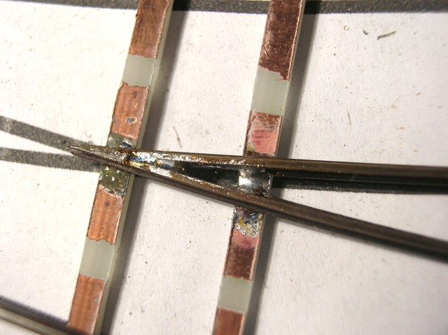
For the mechanical construction of our turnout, we use printed-circuit-board ties at some strategic places. They are cut to 3mm-wide ties using a diamond circle blade. A normal blade would wear off to quickly, due to the glass fibers in the pertinax core. The isolated areas can be etched or filed away.


In our example we make 4 bended turnouts at once. The drawing was made using a cad-programm and printed on some sheets. The drawing doesn't have to be very detailled. Accuracy, however, is very important. On this mould the tie locations are marked using a string of flexible ties. These are held in place using some masking tape, so the tie points can be marked with a pencil.


In order to get the frog angle right, we use a geometric trick. We start by bending a piece of rail at the opposite angle. The paper drawing is the best way to measure this. The angle should be acurate, the rest of the rail can be straight for now.


This bended railpiece is fixed in a machine clamp, with the railhead just above the clamps. The upper part is now completely filed off, so we get ourselves a piece off rail that is nearly broken.


After this filing de rail is bended over in the opposite direction, the rail thus becoming a sharp point. This bending is best done one the mould, so the frog parts are level. Using a pair of tweezers, the frog shape can be adjusted.


In case we filed the rails to far and broke them: this is not that bad, although alligning the frog point will be a bit trickier. The frogpoint is now soldered to a first PCB tie.


The soldering itself is done in two steps: after cleaning the joint is tinned using sodlering paste, with a small piece of resin core soldering the actual bond is made. A second tie is soldered as well to get a solid frog.


The turnout points can be filed to shape now. The drawing shows the two planes that should be filed away: one long vertical plane (blue) and a shorter diagonal (green) The length of these planes depend on the turnout angle.


We use a piece of rail that is long enough to include switch point and closure rails. With the turnout point at the right spot, we mark the place where this rail should be bended. The angle can be read from the drawing.


Soldering this frog wing is a very delicate job, often not succeeding at first. The rail should be alligned perfectly, both horizontal ànd vertical ànd should have the right distances to the frog point. An NMRA gauge is almost nescessary to accomplich this.


Now the third frog tie can be put in place, and the second closure rails can be bent, cut to length, and soldered in place. Again, now is the time to houroughly inspect and measure your construction. If nescessary, use your soldering equipment to re-mount any faulty pieces. The frog is essential for a wel-functioning turnout.


The turnout points need a corresponding space in the guardrail to fit nicely. This is relatively easy to file away: Just don't dammage the top of the rail, as this can cause derailments.


The guardrails can be fixed with two PCB-boar ties. Solder these only on the outsie of the rails. I used PCB ties with a copper-free space of 17mm.


The outer rails of the turnout can now be soldered to the frog ties. Some additional ties between the frog and points make the construction a bit more sturdy. Now the guardrails can be soldered. A spare bit of rail, cut and bent in shape...


... is soldered near the outer rail. For the right disatnce, the NMRA gauge is a very helpful tool.
If you're constructing a turnout for a hidden section, the next few steps can be skipped.


All the ties can be made from circuit board material, but wooden ties are a lot more realistic. I used strips of 2x3mm wood, cut to length according to the design drawing. They are put in place on the drawing.


Without shifting the wooden ties, we remove the rails and brush some contact cement on the rail bottoms. Don't mess any glue at the points! Now the whole rail construction can be replaced on the wooden ties and, using some weights, the glue can set.


After this fase, our turnout look a lot better. Any glu remains can be trimmed away with a sharp hobby knife.


Some painting: the PCB ties are painted dark brown (Tamiya XF-10) after thoroughly cleaning them.


The wooden ties are coloured chemicaly. The "paint" is made by putting some steel wool in vinager and letting this mixture react during a week or so. The liquid will get a rather dirty brown/green colour, ideal for our purpose. Using an old brush, paint it in several layers, letting the liquid dry and react with the wood each time. This way we get a beautiful wheathered look.


De points of our turnout are set using a railroad tie. We need a rotating joint to allow for free movement. A brass nail is used as a pivot axis. These nails are sold at the local do-it-yourself shop. Using a metal saw blade, we make a notch halfway the nail at a tie-thick distance from the head of the nail.


The rest of the nail is filed at an angle, thus becoming a small piece (see the photo). A piece of circuitboard (without the copper) is cut to size. At the middle and at the right distances, a total of three holes are drilled. The two side holes will hold the nails in place.


The tie can now be soldered to the turnout points. Use a lot of tinning fluid and few resine-core solder. We need a solid joint without too much thickness. Any excess van be filed off carefully.


Some space is made in the subroadbed to allow the tie free movement. The hole for the steel wire can be best drilled now, too. Next, the turnout can be glued in place after soldering feeding wires to the rails and frog.
Clamps hold the turnout in place while the glue sets.


The rail spikes are still missing. They aren't too hard to construct ourselves, though. We start by winding a 0,5mm wire round a piece of 1,5x5mm styrene. When we cut this bent wire, we get nice little hooks, usable as rail spikes.


A 2mm wide, 0,3mm thin sheet of styreen is marked every 2mm. After drilling 0,5mm holes in these places, we cut the strip in square pieces.


The ties are drilled too at half a mm from the rails. Through these holes, our home-made nails are fitted and pressed against the rail feet.


Besides making our own nails, we can recover some from spare plastic ties. A sharp chissel blade is the perfect tool for this.


These plastic pieces can be glued in place. A bit of black paint make for a realistic-looking fixation.


After ballasting and wheathering, our turnout is finished. All we need is some sort of hidden switch motor.

©2005 Gerolf Peeters - updated 24.01.2013 See: laying track - Turnout engines