Touch-switches on the control panelsI choice to have touch-switches instead of normal tumblers or pushbuttons for the following reasons:
|
 |
Of course, touch-switches cost a lot of time and effort to construct, but the
money I saved was considerable: I needed about 300 switches, so this saved me
about 270 Euro!
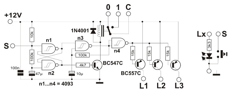
The switch itself reacts to body-part touching (i.e. a fingertip): This way
an interference signal is picked up. This is amplified and rectified by two
transistors. The condenser and resistor make a low-pass filter, so at the input
side of the 40106 a "clean" signal is present. The 40106 inverts the
signal to a proper digital output. Touching the sensor input generates a +5V
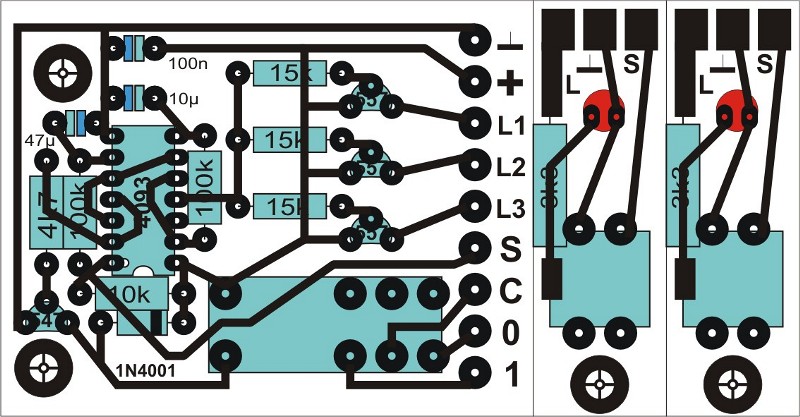
output. As there are 6 Schmitt-triggers in one 40106 package, on each circuit
board six of these schematics are build.
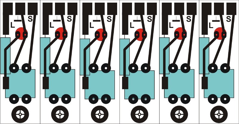
The contact point consists of a simple small brass nail. The flat head can be
touched; on the nail rod a short (to prevent interference) wire connects the
contact to the circuit board. The 3 mega-ohms resistor is added mainly for security
reasons: after all, it is to be touched safely, not to cause electrocution!
I wanted to build them earlier, but as the layout became more complex and less easy to reach to each part, it became an absolute necessity. As it happens very frequently in real life, we seem to need to have a few accidents before a problem gets fixed. This is not a real excuse, but I needed to have several emergence buttons on the "outside" of the layout - the 'fascia'. This wasn't constructed until the summer of 2004. By then some engines and cars had reached the 'urgent repairing'-state.
 |
|
 |
|
 |
|
 |
|
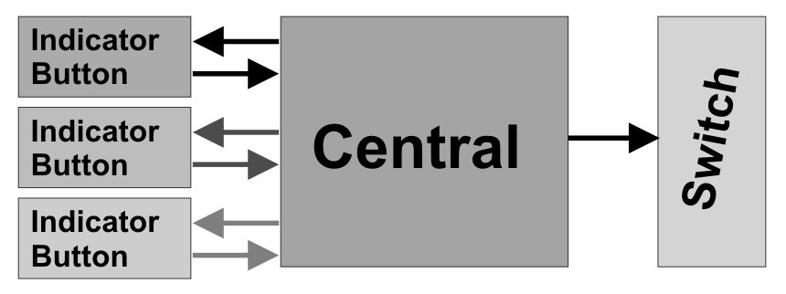
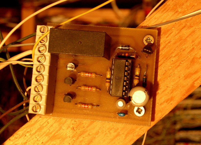
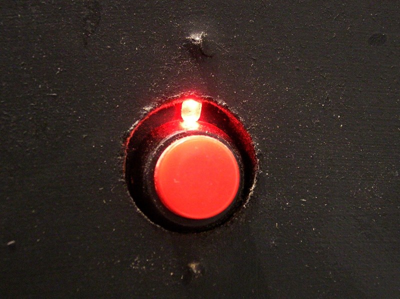
About 15 red-colored pushbuttons where placed on the inside of the layout, the control panels and on the fascia, and connected to the main circuit board. The schematic (left picture) shows this central board. It receives a negative pulse from one of the pushbuttons. This sets the flip-flop and causes the relay to disconnect the clock for all speed controllers, causing all train traffic to stop at once. When this emergency condition is active, LED's near the buttons start flashing. When one of the buttons is pressed again, but longer (more than 5 seconds), the circuit resets, and the LED's light up continuously. This allows the buttons to be found in the dark as well. The right hand side picture shows an installed emergency button.
| ©2005 Gerolf Peeters - updated 24.03.2010 | See: Control panels |