Etching
Chemistry on brass
This was published in Modelspoormagazine 85 en 86. More information can be found there.
The earlier article summaries are at the end of this page
Etching, a short story:
The following drawings depict a metal sheet with a photosensitive layer during the etching process.

This layer is illuminated with utraviolet light(1) The sheet (orangje, 4) with the sensitive layer (blue) sits between printed transparents (grey, 3) with the printed side (black) towards the sheet. This sandwich is clamped between sheets of glass(2)
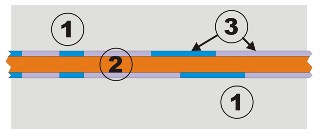
After lightening, the sheet is developed in a fluid(1). The sensitive parts of the layer remain (3), the other parts are dissolved, so the sheet now misses some protection.
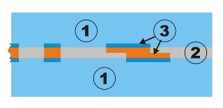
Now the sheet is submerged in an etching fluid (1), where the protected part(3) stays intact, and the non-shielded part(2) is dissolved by the acid. |
Some theory: the etching process
Etching, as used in building models, is chemicaly "attacking" a metal sheet in order to create parts for modeling. This attack is done by an acid, but we don't want to disolve the whole sheet, but just parts of it. So, we need a protection: the shielded part is not etched, the other parts are "eaten" by the acid. This way, we can sculpt a sheet one-sided, or cut out shapes - as called through-etching.
The acid-proof shield is made using photographic techniques: A photosensitive layer is developed using another chemical fluid, non-agressive to the metal it shields. This layer is lit through a partly printed transparent layer: the ink shields light, non-printed parts let the light through, changing the photosensitive layer so it can be developed.
Some warnings before you do any etchng::
- Keep the fluids out of range of children, pets, ....
- read and live up to the user manuals
- if there is any fysical contact, especially to the eyes: contact your doctor.
- Protect yourself: old clothing, disposable gloves, safety glasses,
Step 1: What do we want to build?
Without describing a specific project, let me explain what the possibilities of the technique are. Etching is done through or on a flat sheet of metal, so you can only make things that are cut out of a sheet are carved to halve the depth of the sheet. This can be a line, along which we can bend the part
Another restriction is the thickness of the sheet. There is a limit, as during etching the acid creeps under the protective layer. This influences the making of small parts and details.
|
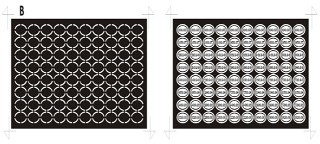
Step 2: De design drawing
We must draw a design, giving us two transparent sheets: one for each side of sheet. Both part must be aligned and mirrored towards eachother. We must get the printed part (the ink) as close as possible to the photosensitive layer. It's obvious we need a computer to help us drawing. This can be almost any model, as long as you have a vector-type drawing program, such as AutoCad or CorelDraw.
The printed light-shielding layer should be as dark as possible, so you will have to adjust yout printer settings. Hold the result against a light source, and you will see when it's OK. Laserprinted sheets have an advantage, as you can darkened them with a washing of pure ink and wiping it of before this is dry. The rougher printed parts will grasp the ink, the smooth non-printed parts will be wiped clean.
Some other aspects need our attention: Is the photosensitive layer positive or negative? This means you might have to invert your print. A positive layer means that the printed parts won't be etched, a negative layer means they will dissolve. As we will cut out pieces, we must take care the parts will stick together in a frame, so we won't have to do any fishing up parts in our etching fluid. A 2mm wide frame is OK, and each part will have to be connected with this frame and/or with the other parts, using small non-etched strips that can be cut after etching.
|
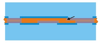
Another issue is under-etching. During etching, and particularly when using thicker sheets, the fluid crawls under the protective layer. This layer should therefore be drawn a bit wider then the desired result. 40% of the sheet thickness should be OK. A last issue is: don 't waste etching fluid. It is rather expensive, and not ver friendly to our environment. Get as many parts as possible drawn on a sheet, and fill in the rest with black spaces.
Step 4: Aligning the printed sheets
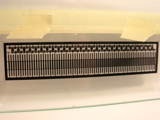
We have to make a little folder, fittting around the metal, with the printed sides of the transparents on the inside, and perfectly aligned to eachother. The markings we've drawn help us to do this. Using masking tape on one edge, stick one transparent with the ink side up on a piece of glass. The second sheet, ink side down, gets another piece of tape on the same edge. Using back lighting, carefuly align it to the first sheet and stick it to the other sheet's tape.
|
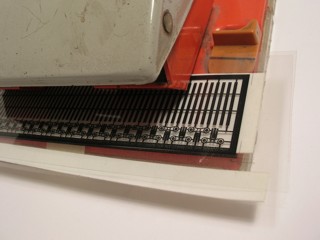
Remove the two transparents, now taped together. The non-taped edge of the masks is pierced by an office perforator, which is now blocked in its closed position. I used a nut and bolt to secure the closed position. Now, the tape can be safely removed.
Using a sheet of plastic with the same thickness as the metal we want to etch, adjust the distance between the sheets by sliding the top mask a bit up along the piercing axles of the perforator. A second, small piece of plastic with the same thickness is now glued between the masks, along the bottom edge of the printed design. This plastic will block the distance between the masks and helps us keep the metal at the right spot.
When the glue has set, you can safely open the perforator, and trim the edges of the masking folder.
|
Step 4: A suitable light source
It's certainly worthwile building your own device. We need a specific type of ultraviolet light, its wavelength a bit shorter then visible light. Ultraviolet light is divided in 3 types:
UV-A: causing damage to us (burning, skin cancer, ...)
UV-B: tanning our skin (as used in sun-bathing)
UV-C: its wavelength even shorter, used for desinfecting materials
Sadly, the photosensitive layer agrees mostly with UV-A, wavelength 380 nm, to be precise. Solar tanning tubes hardly emit this light, and are not suitable for us.
A point-source light is best, as it sends almost no indirect light, but should be placed at a reasonable distance to get zenital radiation. But, with this distance, their intensity drops. A specific source of UV light is our sun. It sends parallel light beams, but not reliable as a continuous light source, due to our climate.
Eventualy, we found short light tubes with an acceptable wavelength and radiation level. They're used in electronics, to help construct printed circuit boards.
|
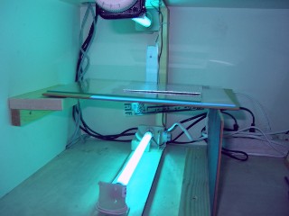
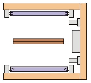
As our metal sheets have a photosensitive layer on each side, it makes sense to put a UV light source on both sides, of course at the same distance from the layer. As the emited light is possible harmful, we should shield the light while using it. I rebuilt a shelve in a closet. A glass sheet on both sides holds the metal sheet in position during lighting. A U-shaped wooden frame supports the lamps and their power source.
|
Step 5: Clamping the transparents to the metal sheet
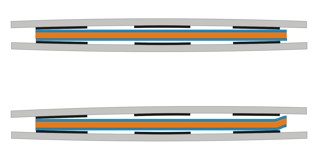
To light the photosenstive layer in a proper way, the mask should be tightened to the metal sheet, as any room between will alllow "stray" light beams to affect the result. We therefore put sheet in our transparent envelope between sheets of glass. We don't put any presure on the glass, as it will bend a bit, leaving room in the middle. The drawing illustrates the effect. As the metal sheet might have some bumps, this effect occurs even more.
The problem is even more important if you want to etch very thin lines. |
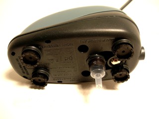
The sollution is "nothing", no air between the sheets. By pumping away the air between the sheets, the outside air takes care of a very powerful, effecctive pressure (1kg/cm²). An air pump is used further on to mix etching fluids. The pump we used has an air entrance in its bottom side. A piece of a siringe is used as an adapter between this inlet and an airhose.
|
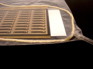
A sealable plastic bag is our vacuum chamber. In one corner, I made an air-tight adapter for the other end of the hose. To assure an equal withdrawal of air, use a wool wire, placed around our brass-and-transparant sandwich.
|
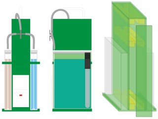
Step 6: A home-made develop- and etching device
Why make this (and not buy it) Well, shop around and you'll see what a (poor) quality you get for (too) much money. Let me tell you what I expect from a good device::
- Transparant containers with enough room for fairly large pieces
- Constant heating of the etching fluid, +/- 50°C
- Adjustable movement in both fluids to assure equal results
- Suspension system for various sizes of metal sheets
- Easy to maintain, sealable when not in use
- Safe, handy, economical, ergonomical, ...
|
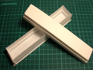
An etching conatiner should be high and wide, but have a relativey small volume, so not too deep.
I had the containers custom-made: acid-resistant, 25cm high and 16 wide, but with a volume of 800cc. The design of the rest of the device was tailored according to the size of these containers.
The central column and some strips of styrene hold the containers in position. This central part houses the airpump and the electric parts: switches, fuse, ... A one-way valve protects the airpump from any liquids creeping in. A three-way air regulator on the outside of the central column is used to control the amount of air going through the conatiners.
The
covers for the containers are home-cast using silicon rubber. The mould for this casting was easily made from scrap styrene, its dimension were measured from the container's size.
|
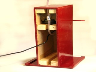
The picture shows the woodwork finished and a good-quality paint is used to protect it. The front panel is screwed (not glued)
to allow any maintenance. The airpump and its one-way valve is mounted, the airhose is lead through the roof of the cabinet. |
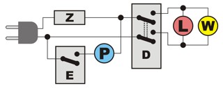
The electricity is pretty straightforward: The power supply at left, a fuse (Z) keeps the device safe. A single-poled switch controls the pump (P), a double-poled is used for the heating device (W).
Keep safety very well in mind while wiring everything. After all, high voltages and fluids don't agree. Take care wires can't get loose and cause a short-circuit, and no fluids can reach them.
|
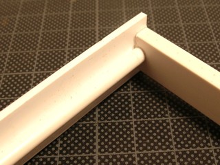
To get motion in the fluids - and thus an equal concentration mix - we will stirr them constantly by blowing airbubbles through the chemical sollutions. At the bottom of each container, a rectangular tube of styrene gets tiny drilled holes. The air supply comes through a round styrene tube. These styrene profiles are glued inside the container. |
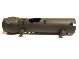
We want the etching fluid to reach - and hold - 50°C. I used an aquarium-type heater. Its placeholder has to be mounted inside the container, and allow space for the lids.Because of this, we have to mill a hole for the "on"-light to shine through. Screw and glue this placeholder well, so no liquids can pass through the mounting holes.
|
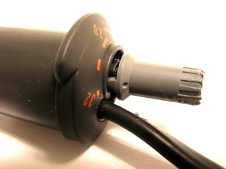
As an aquarium-type heater is limited to about 32°C, we have to "influence" its reach. By pulling out the regulting knob, it might be possible to turn it further then the pre-scaling.
|
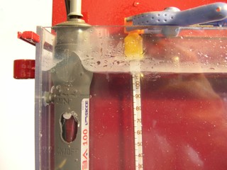
To adjust the temperature, we need an external thermometer, dipped in a water-filled container. Step by step, adjust the knob until the desired heating is reached and held. Now you can secure the knob with some thick glue.
|
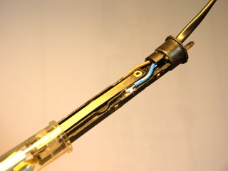
It's possible that the above method isn't enough, and you'll need a rougher approach. Dismantle the device and gently bend the metal spring that measures and switches the heat. Mount everything in place and try it out with the external thermometer, repeat this until you're satisfied.
|
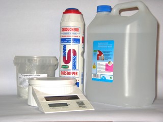
Use demineralized water. The developer is NaOH, a 1% solution (800cc means 8 grams) Fill the tank, mix it with air and gently add the powder. This stuff is agressive, so be carefull!
The etching fluid is a 20% solution of Na2(SO4)2. Fill the container for 2/3, heat and mix it, add 160 grams of the powder and fill the tank to 800cc.
|

Step 7: Measuring lighting time
This is the last preparation before we can use our photosensitive material. As the lighting time depends on your lamps and their position, as well as the specific photosensitive layer, this has to be measured for each type of sheet you use. A simple transparent, with two times the figures 0...9 will do.
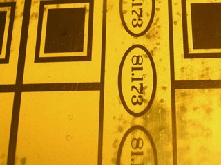
Using a piece of black paper, gradually expose the metall sheet, 1 minute for each figure. After 20 minutes, the sheet can be developed and will show a gradual effect of the light used. The picture above shows the right hand side "3" OK. More to the left there wasn't enough lighting. This means 13 minutes is the best time for the light and photosensitive material used.
Step 8: Lighting
You'lll probably have to cut the sheet to size first. Dim the ambient light while doing this, and use a knife (no scissors or sawblade) to get a smooth cut. The prepared sheets have a protecting foil. After removing this, don't touch the surface and place the sheet between the transparents and into the vacuum bag. Start the airpump and wait for the bag to press against the sheets. Now place this sandwich between the light source and start lighting. Don't shut off the air pump.
|
Step 9: Developing
Remove the exposed sheet, not touching its surface and hang it verticaly in the developing fluid. Start heating the etching fluid, and use the air bubbles to mix the chemicals in both containers. Watch your sheet, as developing goes pretty fast. If this takes longer then 5 minutes, you're developing sollution is probably worn out (or you haven't used enough light).
The sheet is ready when there's a crisp drawing on bare metal.
Rinse the sheet in plenty of water. A nearby sink is very handy for this.
Step 10: Etching
Use as much air as possible in the etching fluid, not splattering any chemicals outside the container. Hang the sheet in the warm liquid. In less then a minute, you should see a difference on the bare metal parts. If this doesn't show you haven't developed the sheet long enough, so take it out, rinse it and develop it a bit more. To get an equal etching result on all parts of your sheet, rotate and flip the sheet every 15 minutes. When using fresh chemicals, etching goes fairly fast. Don't wait for the last piece of metal to vannish, as some other parts may be damaged by then.
Stap 11: Cleaning and cutting the etched pieces
Rinse the sheet carefully after etching. To remove the unexposed photosensitive layer, you could expose it now and use the developer to remove it, or dip the sheet into aceton.
Small metal scissors are the best tool to cut the parts from their placeholders.
|
This subject was published in Modelspoormagazine 45, as a sequel to an article in MSM44.
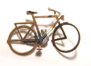
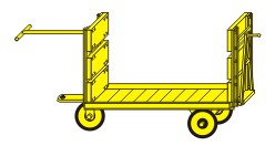
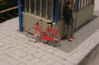
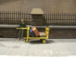
Let's make a platform service car and some bicycles using the etching technique. These aren't to complicated to construct and allow us to demonstrate the etching technique.

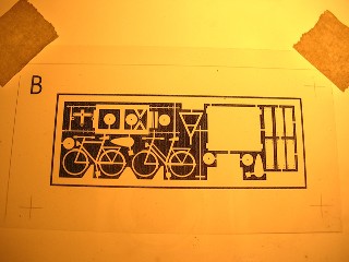
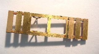
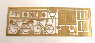
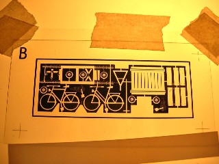
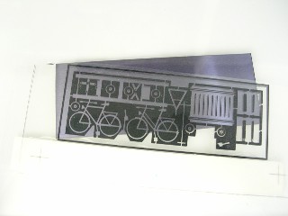
The mask above can be photocopied from Modelspoormagazine 45. Its dimension are perfect for H0. The drawing has to parts: one to use on top, the other to use underneath the brass photosensitive sheet. The little crosses are essential to the drawing, as they will allow you to align the masks.
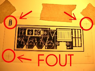
We need a backlight to align the masks. Put the first transparent, printed side up, on the glass surface and tape it on the top ends. The second transparent is placed ont top of the first, printed side down. Align them perfectly. The above right pictures shows this isn't done properly yet. When done, tape it to the glass as well, but again only on the top side.
 |
 |
The brass sheet is 0,3mm thick, so the transparents should have the same distance. We also need some kind of barrier to position the sheet easily. A 0,3mm thick strip of sheet styrene will do the job. Glue it between the transparents, aligned with the drawing's bottom line in the, using contact cement. Let the glue set overnight, and remove the sheets from the glass surface. Remove the tape, and trim the top side of the sheets.
We need a 28x75mm piece of brass photosensitive sheet. Remove its protective covers and align it between the two transparents, without touching its surfaces. Put this 'sandwich' between the lighting frame of our UV-lighter. Start the nescessary lighting time. Switch on our home-made etching tool so the fluid can start getting warm.
 |
 |
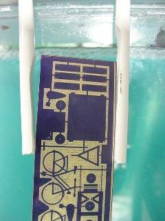
Developing is done using a plastic pare of tweezers or disposable gloves. With the air pump switched to the development tank, proceed carefuly, checking regularly to see if the development proces is finsihed by rinsing the sheet with water.
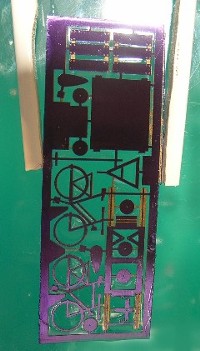
Switch the airflow to the etching tank, lamp the sheet between the styrene placeholders and submerge the developed brass sheet. After some minutes, you should notice the chemical reaction has started. If not, the sheet hasn't been developed enough or the etching solution has worn out.
The whole etching proces takes some time, typically some hours. Keep a good watch on the sheet, as things can proceed very quickly once the first holes appear. Don't wait until the last bit is etched, as some vital parts might have disappeared meanwhile.
 |
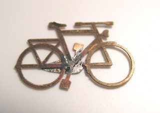
With the brass sheet fully etched, lets start building our models. The bikes are built first, as they aren't to hard to do. Release the parts by using fine scissors or a sharp knife. try not to bend teh parts, and file away any irregularities.
Only one part has to be attached: the chain and one pedal. You can glue them, but soldering is better, as we need to do some bending and a glued connection might break loose.
Using tweezers, carefuly bend the pedals so they are square with the frame. The steering tube is a bit trickier, bent it as a whole, and shape the ends afterwards. If you choose to adjust the front wheel, remember the steering tube should be aligned with it.
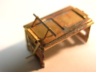
The platform service cart is a bit more difficult to construct. Start by bending the sides of the bottom part, to get its typical form. The folding lines are etched, so bending the model at the right places shouldn't be to hard. Now bend the wheel axle supports and the coupler holders to shape. the wooden back- and frontsides can be soldered on the frame now.
Next poistion the bottom, bend the side parts to shape and solder the bottom to the frame.
 |
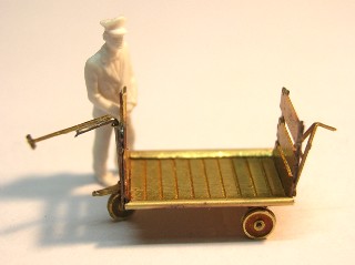 |
At the car's back side, a plate can be bent to form a hinge. This will hold the rear coupler, which can be placed horizontaly - to pick up another car - or verticaly. Don't tighting the hinge to much, so it can move a little.
The wheels are composed of two halves, which are soldered together. Once connected, drill a 0.5mm hole in the wheels and axle supports. The axles are made of 0.5mm piano wire. Glue the wheels to them with a tiny drop of cyanoacrylate glue.
The front wheelholder can now be bent to hold the front wheel and its axle. A shaped piece of pianowire becomes the front steering lever. If you glue it carefuly, the lever can be rotated freely.
Using an airbrush, the car can now get its yelow base colour. the wheel tires are painted black. A little washing should give the car a used look.


