Many modellers think soldering is beyond their capacities. Still, when knowing a bit more and practicing, it isn't that hard to do. On this page, I want to lower the barrier, or allow you to fine-tune your technique.
As it is a very broad subject, I divided it into three parts, each with theoretical and practical information. The first part describes basic knowledge and resin-core electric soldering.
"A technique in which two metal parts are joined using another metal and a heat source". This means there's a difference with other joining techniques:
Gluing: the joining material isn't a metal (the joined parts can be another material, too).
Welding: the joining metal is the same as the joined metal.
Another issue is the use of heat: The connecting layer is melt, and after cooling (to a solid metal) the joint is made.
Soldering uses a metal with a relatively low melting point, mostly a tin-based alloy. It has three melting fases:
Liquid: higher then the melting point.
Plastic: deformable, like clay
Solid: once the metal cooled down enough
Especially the plastic fase is important, as the joint is vulnerable at this stage. Any movement causes a fragile, dull-looking connection.
Solder for hard-soldering: This has a relatively high melting point, in the range of 500 to 800°C. It is used in plumbing, jewelery and space engineering.
Solder for soft-soldering: The kind we use in modeling, not long ago mostly a lead and tin alloy. As lead causes health risks, it should be banned as much as possible. It is replaced by other metals, with a slightly higher melting temperature.
These can have a resin-type or a liquid consistency. They liquify the melted metal, so the junction surface is as large as possible. Furthermore, it takes care of removing oxides.
Heat: Is nescessary to get the right temperature for the metals you want to join, and the joinig alloy you apply. The temperature shouldn't be too high, as this causes oxidation, and eventualy burning. Ideally, the temperature applied is about 10 degrees higher then the alloy's melting point.
Hold it
Don't move a joint while the solder cools down.. Especialy during the "plastic fase" any movement means damage. Use clamps or try to speed up the solifying proces by cooling the largest soldered part.
Clean work A third cause of bad joints is pollution. Each "alien" material causes an alloy to not harden homogenically. Degreasing, polishing, .... are mandatory.
Rust? Not unlike other pollution, metal-rust is a hazard. Clean everything, and let the flux take care of oxidation during heating.
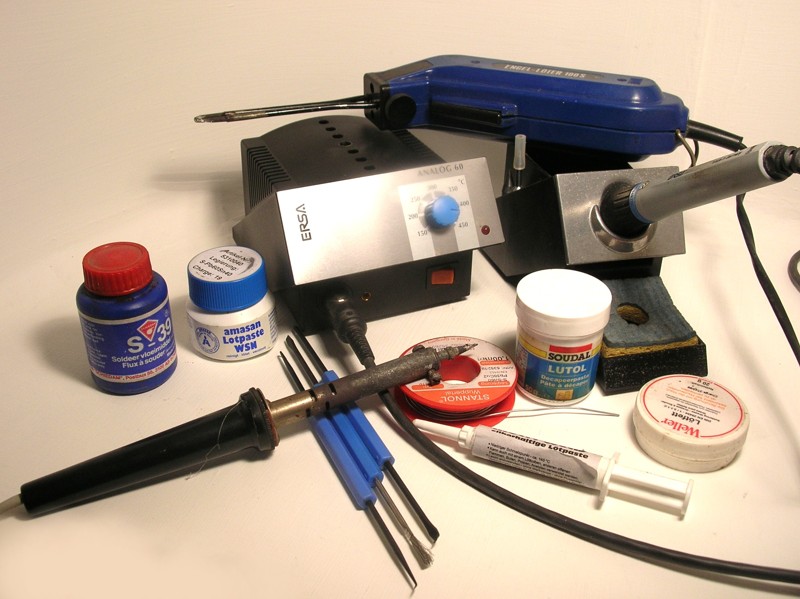
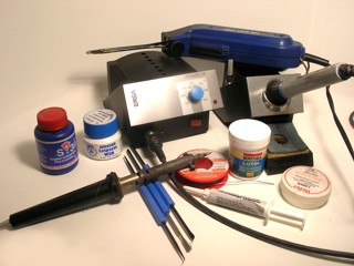
You need a heat-source to solder. Thsi can be an (electric) soldering iron, gas-powered, or a specialized tool like a resistance soldering device. Electrical soldering irons have different aspects:
Soldering gun: This is in fact an electrical transformer and a switch. The current is almost cut short at the tip of the tool, causing an intense local heating. I don't recommend such a tool for a beginning modeller, as it is very tricky to get the timing right during soldering.
Soldering iron: This tool has an electrical heater near the tip, and most of the time no switch. The iron's tip is heated gradually. For modeling purposes, 25 Watts is generally enough, tools with over 50 Watts are to powerful. Try to get a tool with exchangeable tips. They are not expensive and, if properly maintained, they last a lifetime.
Soldering station: This is in fact an iron as described above, but with a temperature controller. Different soldering tips can be applied. Most of the time, they are a bit more powerful, so they heat up more quickly and their temperature stays steady while soldering. Generaly, they are a bit more expensive but should last a lifetime. It is an ideal tool for the serious modeller.
No matter what type of device you use, it's tip is the most important part. It should be kept undamaged and clean to get the best results.
Damage: Suppose you've soldered something, but the parts aren't positioned right. You could re-heat the joint and use the soldering iron to push the part to to right location. The tip of a soldering iron is made of a rather soft metal, meant to conduct heat as best as possible, so it is not as strong as a crowbar. Furthermore, the (mostly copper) tip is coated with a layer of silver to reduce oxidation. This coating cracks when the copper underneath is bent. So: use your soldering tip gently.
Make and keep it clean: Cleaning is best done with a rough, moisted piece of cloth.
A bit of water keeps the cloth from burning, Don't use a wet one, as this causes sudden cooling of the tip, and possibly damage. Soldering flux prevents oxidation and protects your soldering tip, so don't clean it after soldering, but before making a joint.
|
|
We start with the most simple connection: joining two wires. Use a soldering iron or station, and thin resin-core solder.
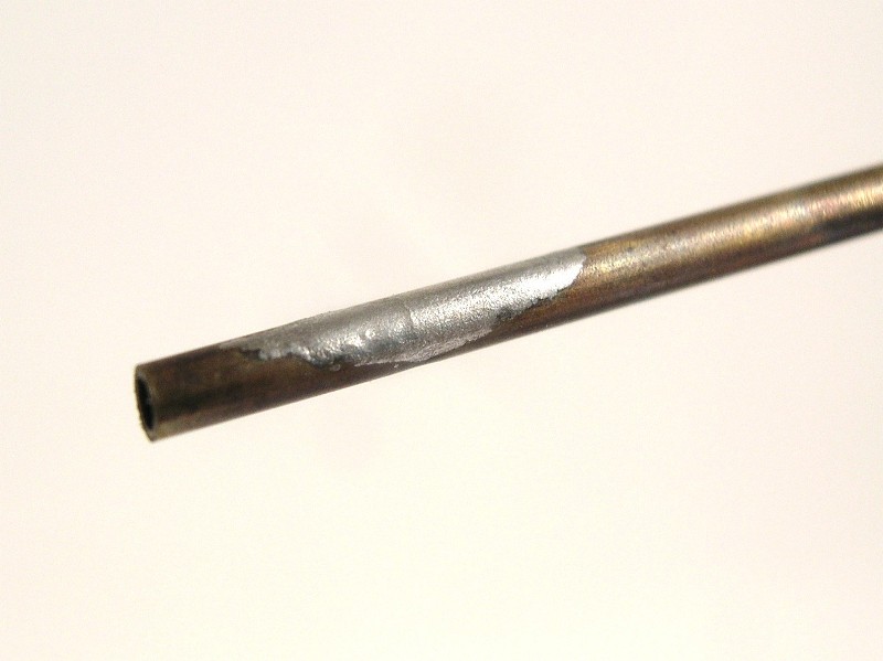
Tinning is aplying a thin coat of solder on a metal surface. This can be a good preparation for a soldered joint, especialy when soldering larger parts. This is done quite easy: Using a hot soldering iron, put a bit of resin-core soldering wire on its tip, heaten the metal and gradualy add more tin. Bij het vertinnen The hot tin floats over the metal surface. let it cool down, and remove the flux residu with a hard brush or a bit of aceton..
 |
 |
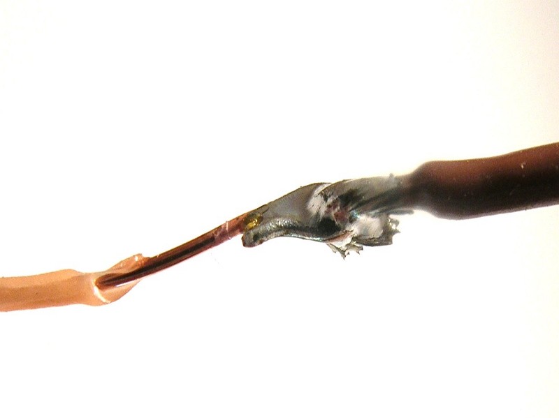
Remove at least a halve centimeter of their insulation. If the wire consists of several thin metal threads, you should twist them to hold them together. Bend both wire ends to form hooks. These will prevent the joint from moving during soldering. Using a hot iron, and resin-core solder, the next step is done quicker then I can tell it:
Melt a tiny piece of solder on the iron's tip and apply it to the joint so it heats up.
Once the joint is hot, add a little extra resin-core solder and watch it float into the joint. Remove your iron and let the connection cool down. All of this is done in seconds. Simple, no?
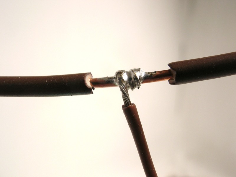
Often used while wiring a model railroad: getting current from a thicker feeding wire. Don't cut this main wire, but strip its insulation about 1 cm. Strip the thinner wire for at least the same length, and twist it around the feeder, to get, once more, a mechanicaly solid construction. The next step is equal to the above and quickly done: rsin-core solder on your iron's tip, heating the joint, add solder, and cool down...
 |
 |
When wiring your model railroad the proper way, this has to be done on lots of locations. Most model rails can be soldered using resin-core alloys, for steel rails you will need a specific flux (e.g. S39 for inox).
When your is located in a hidden part of your layout, the connection can be "ugly", as long as it is functional. Your feeding wire can therefore be attached to the rail's outer side, under its head. Tinning both parts of your connection in advance is useful, as this reduces the chance of melting your ties. The actual soldering is done by pressing and heating both parts together, and adding a bit of resin-core solder.
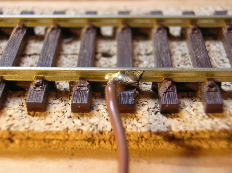
When your track still has to be placed, but in a visible part of your layout, it's best to solder your wire underneath the rail's foot. Slide the sleepers a bit away, and connect your wire as described above. After laying the track, the connection will be hidden by your ballast..
 |
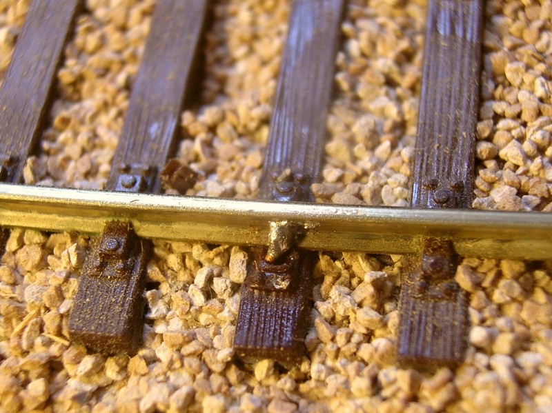 |
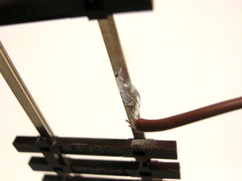
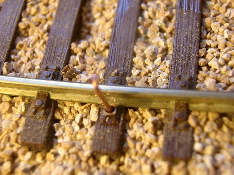
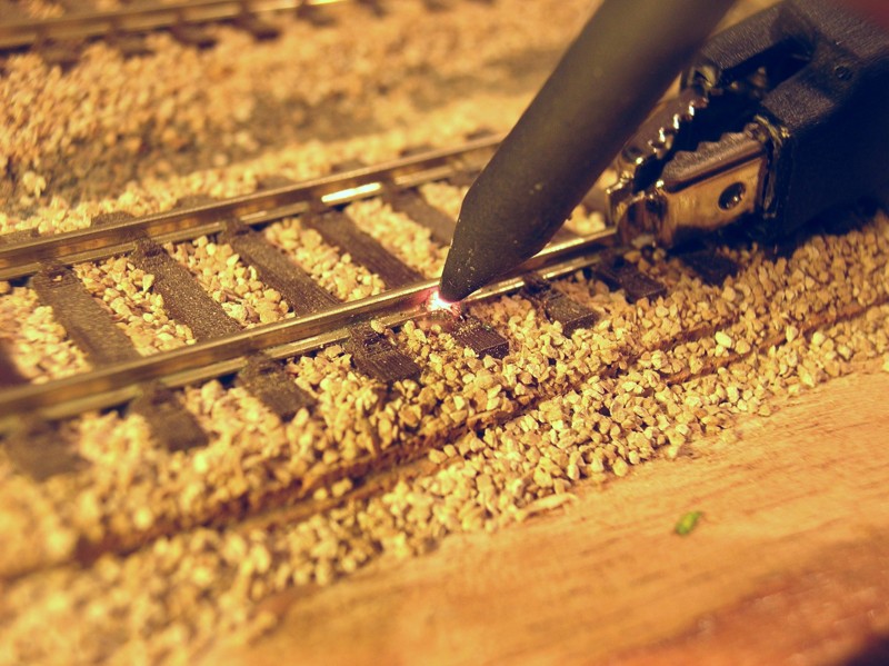
A last situation: your track is already placed and ballasted in a visible part of your layout. Remove the little notch that imitates the rail's fixation, and drill a small hole through the sleeper and the subraodbed. A piece of solid wire is bent to shape, to imitate the notch we just removed. Slide this wire through the hole, and place a tiny piece of resin-core solder between the rail's foot and this bent wire. Using a hot soldering iron, press the wire against the rail. The solder wil melt and attach the wire.
Clean any flux residue, and with a dab of paint the connection will be hardly visible.
Now that we know the basic stuff, let's move on. I'll discuss (a lot of) aids for soldering, and another heat source: gas.
I already discussed these, but now I'll do this a bit more thorough. Generally, there are two kind of products: liquids and fat-like resins. They share one property: they are sour. The acid acts against oxides. The liquifier can be present inside your tin (like in resin-core solder), but can be added seperately, too:
Soldering water – liquid liquifier: This can contain sulfur, phosporic, ... but most of the time an organic acid. Of course, these products are agressive, so be very careful with them. If spilling some on your skin, rince the affected area thoroughly with water and - if you have any doubts - see adoctor. As the products stays corrosive after applying it, your soldered joint should be rinced as well. This means using these products on your layout can be troublesome: you can't rince your entire layout ...
Soldering fat – Purine and other resins: Less liquid and more sticky, these can be "solified" liquids or natural resins. asthey are sour, too, read the above warnings.
How and why using liquifiers? When we have excellent ready-to-use products, why should we bother with additives? Well, two reasons: your soldered joint can have "failed", and you can use it to prepare a joint. The liquifier 'wears out' after about 5 seconds. Modellers - and not only beginning ones - making a 'difficult' connection can easily go beyond his time limit, resulting in a 'bad' joint, containing oxides. Adding more resin-core tin isn't the sollution, you only need the resin itself. So: heat it up, add some liquifier, let it melt for a short while and let it gently cool down. Preparing a difficult connection with some sort of liquifier is another option, but keep in mind that you have to clean more afterwards. Resins are applied with a toothpick, liquids with an old paintbrush.
 |
|
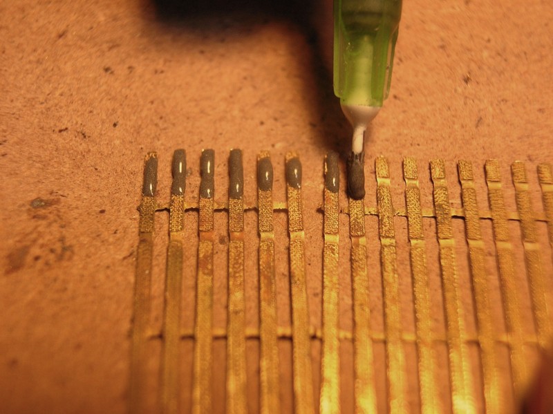
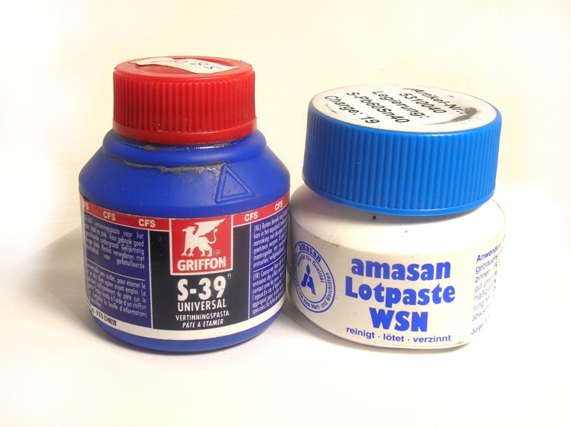
This is in fact a mixture of a liquifier and very fine grinded tin. Its consistency depends on the amount of powdered metal, and the sort of liquifier used. As it is a mixture, these products should be stirred thouroughly before use. Soldering paste is mainly used in the (industrial) production of electronic circuit boards. Search for "reflow-soldering" on the internet and you'll know what I'm talking about.
It is a very useful product in railroad modeling, too, and its most basic use is tinning a surface. The picture shows one way of doing this: a small siringe, fitted with a shortened thick needle acts as a dispenser. Heating is done best with a gas-powered torch.
The thicker soldering paste is very suitable to connect well-fitting parts. Think about joints you would make with cyano-acrylate glue, but that should conduct electricity.
 |
|
"Everyday" maintenance is expalined above: rubbing the tip to a moist, not too soft piece of cloth is OK. Suppose you've forgotten this, or forgot to shut off your iron, its tip can be burned and you'll need a "stronger" way to clean it. Remembering an iron's tip mostly has a vulnarable silver couting, don't be too agressive...
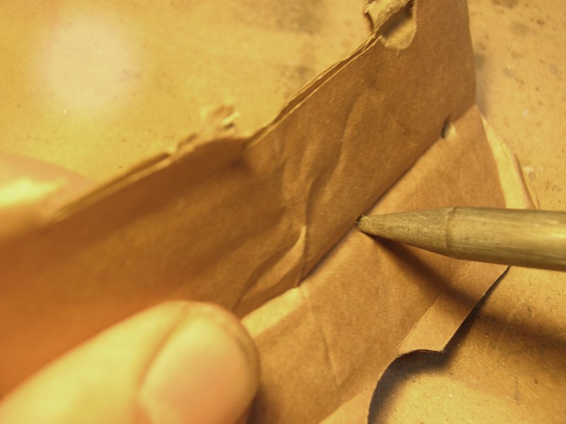
Mechanical cleaning: Brass curls (from using a lathe?) is a relatively soft "spunge" but is more abrassive then a rough cloth. A softer, cheap material is packaging cardboard. Press your hot soldeing tip through it several times, and flux residues are brushed of in a gentle way.
Chemical cleaning: A salmiak stone. This solid - but not hard - material is alcalic, and neutralizes the flux acids. Any high-pH fluid is possible, but remember that these can also cause corrode metals. Preventing is still the best way to go.
your soldering iron: You'll need some form of support for your hot iron. I know people using an ashtray with a piece of not-too-wet felt in it, and that's OK....
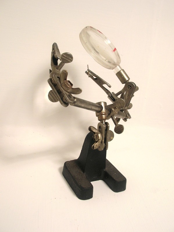
your work: When soldering, we should often have one or more hands extra. Keeping a joint steady while it cools is very important, and you need hands to hold your iron, add solder and/or flux, keep your parts in place, ....
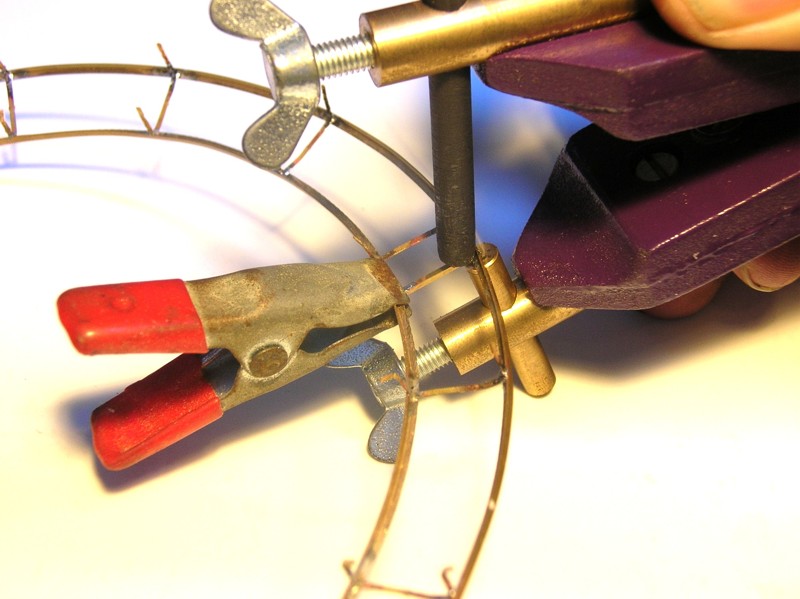
clamping your pieces: a third hand is always useful. This can be pieces of tape, holding parts on a printed design, a vise, or a little tool as shown in the picture above: it consists of two adjustable clamps, and possible a magnifier glass for older eyes...
 |
|
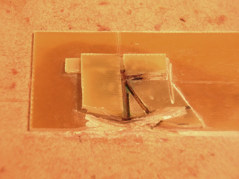
When you need to make the same type of connection several times, a mould is the way to go. I prefer sheets of epoxy to build a mould, as it is a heat-resistant and easy to cut and glue. Another aid is a tool I found at the German “Fohrmann Werkzeuge”, a ceramic board with lots of holes where little steel pins can be placed. These pins, and some other parts, keep your profiles in position while soldering.
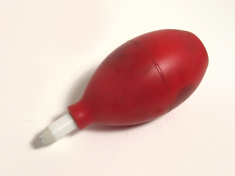
Or: loosening a soldered connection. The first thing to do this is removing as much solder as possible. Heating the joint, and sucking the liquid tin is the best way to do this. This suction can be done with a vacuum pump or a "textile".
 |
|
Gas has some advantages: The energy source is inside the tool, making it more mobile and very suitable for small soldering jobs under your layout. Another plus is the heat range: compared to electrical soldering, much higher temperature are possible. This in turn makes connecting a lot faster, as your parts are heatened faster. A joint can be made before a nearby connection had enough heat to melt and loosen. Because of the higer temperature, your device is faster "ready-to-use". The gas used is a quite common sigaret-lighter fluid, making the device easy and cheap to refill.
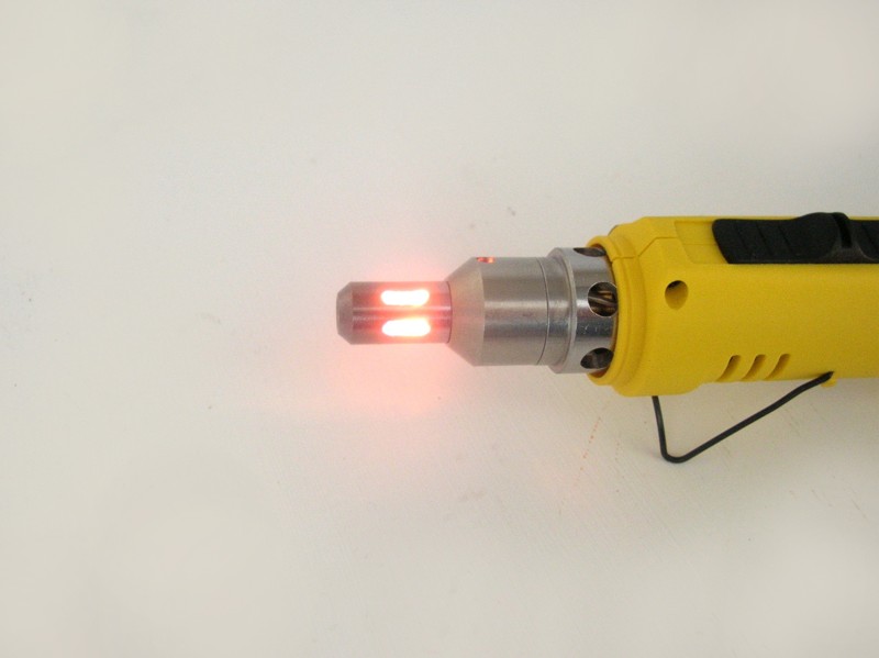
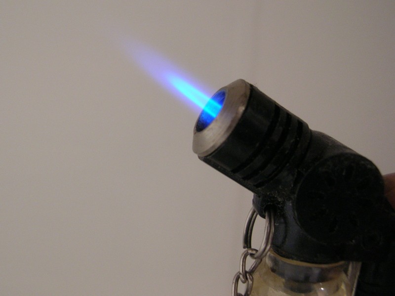
As it's the case with electrical soldering tools, gas tools are developing as we speak, the number and kind of models increasing rapidly. Basicly, there are "open-flame" torches and tools that heat a soldering tip. A torch-like frame is fine for tinning surfaces. A very cheap torch (see picture) looks like a sigaret lighter, but some modifications let the oxigen-gas mix better. The produced flame is quite hot and very narrow, allowing precise modeling.
The devices heating a soldering tip are most of the time sold with exchangeable tips. I bought a mid-range
quality tool. It can be used as "flamethrower", but the flame is too wide to heat small surfaces.
Filling, lighting, regulating,… Before first use, its gas tank has to be filled. Use purified gas to avoid contaminating - weakening - the joint. This gas is sold in presurized canisters with a range of connection adapters. After filling, let the gas stabilize. Lighting the tool is much like starting a gas-powered water heater: Light the flame and wait for the controller to heat up, and gently loosen the trigger. Check your device's manual for the exact instructions. Precise temperature adjustment is, unlike with electrical tools, not possible.
 |
|
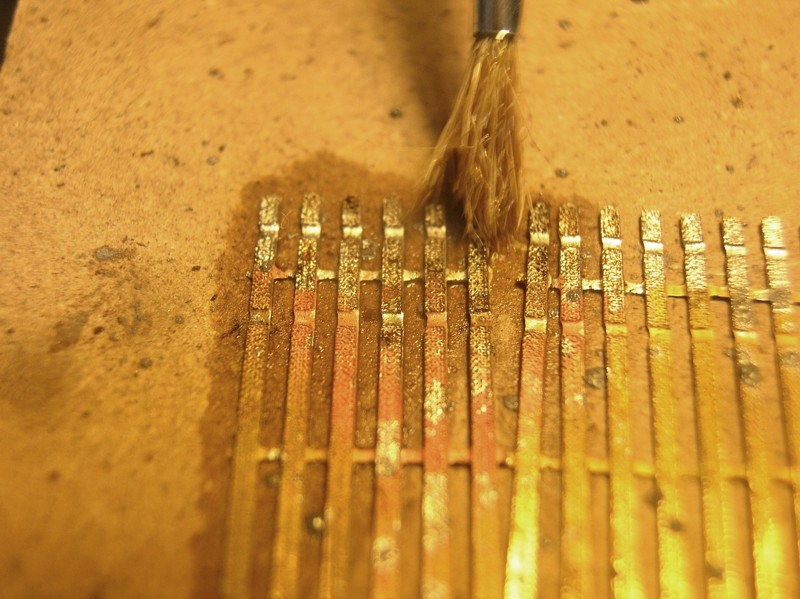
Tinning surfaces: This surface can be a brass part from a kit, a part on which we want a silver-like shine, or the copper wires on a printed circuit board, to prepare it for easier soldering its electronic parts. Soldering paste is the easiest way to go: Brush it, use a toothpick, ... to apply it, and use an open torch or a large soldering tip to heat it. After this, brush any flux residue of in a hot soapy bath, or use aceton.
Soldering brass profiles: In case you use soldering paste, a small siringe is quite handy to apply this product. After some practice, you'll know how (much) to use. Using a (hot) tiny flame, the future joint is heated very fast, not allowing a nearby joint to melt and loosen. Heat the largest part, so both parts heat up simultaniously.
Resistance soldering means: heating your joint by using an electrical currrent through your connection. Various materials have various conductivity. If there's enough current through the worst conductor, it heats up most. We use this property to get the heat where we want it to be: Inside, or very near to the joint we want to solder.
This also means the (considerable) current has to pass freely to our "hotspot", so the feeding conductor's quality should be near-perfect.
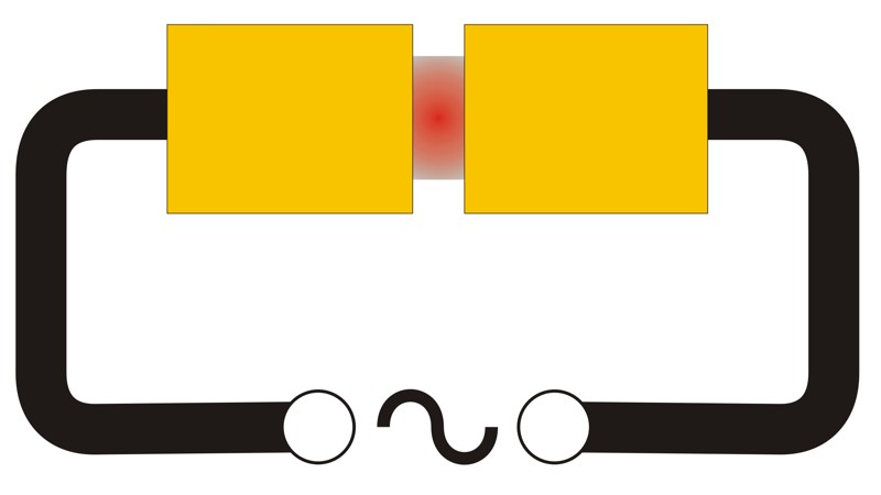 |
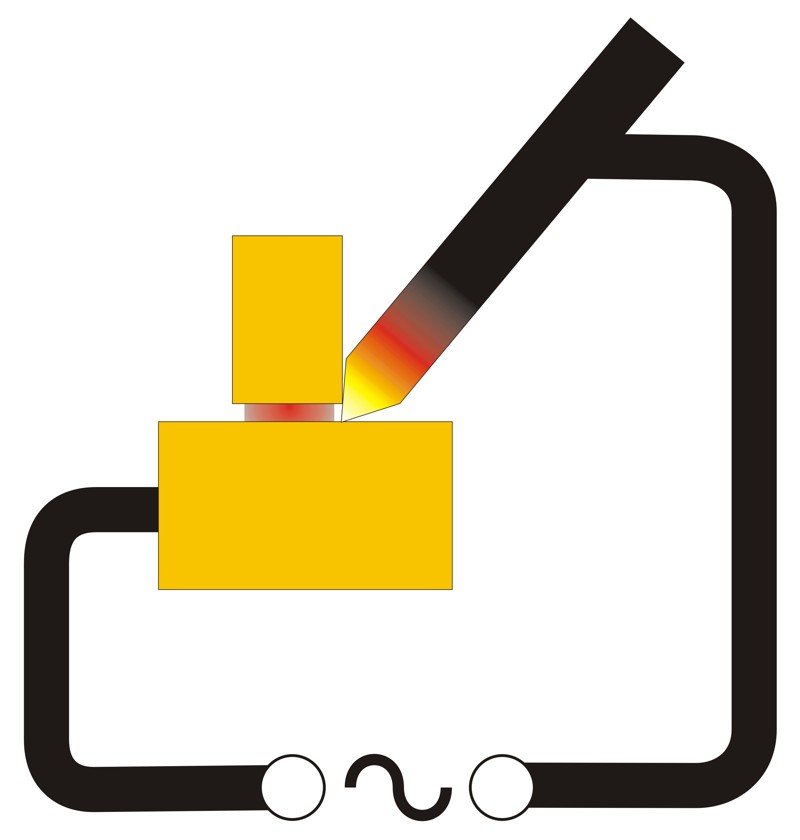
The power source, at the bottom of each drawing, provides the cuurent. At left, the connection itself has the highest resistance (e.g. brass is a better conductor then tin) and heats up. The right drawing shows the most commonly used technoque in building models: a worse conductor heats up very close to the connection we want to make. When appliying current, this becomes a soldering tip and heats the joint indirectly.
The biggest advantage is speed. Preparing the joint takes as long as with another soldering method, but heating it goes very fast. This speed causes nearby joints to stay intact - they just don't have enough time to heat up. Thus, resistance soldering allows complex constructions in a small area. Another advantage is safety: as your heat source isn't constantly hot, the risk of burning things is minimized. The disadvantage is caused by the current: sensitive electronic parts can be damaged.
 |
|
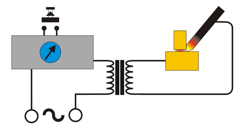
A large transformer converts the power supply voltage into a smaller one, but with an equaly large current. A dimmer regulates the input voltage, and thus the output current. A switch in this regulator allows us to start and stop the current.
|
|
|
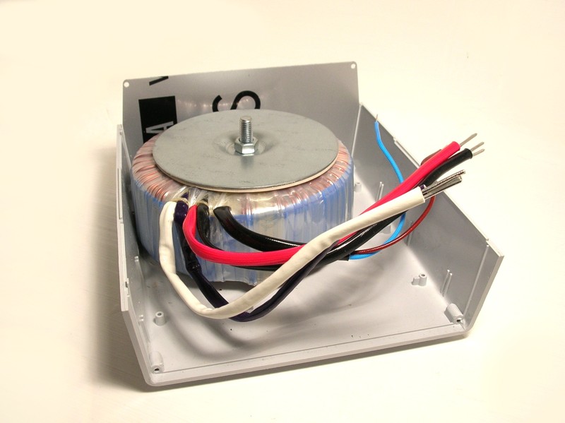
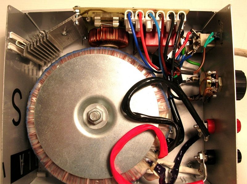
The largest and most expensive part is the transformer. It should produce a low tension, with as much current as possible. The 400VA type gives a 33 amps current. As we nearly short-cut its output, this current gets even higher: double or even close to triple, meaning a possible 100 ampère. As the picture shows, the housin,g doesn't have to be much larger then this transfo.
The housing's front panel holds the connectors and the user interface elements. Think about easy wiring and easy-of-use when designing the front panel. Don't be to greedy when spending money for the cables and connectors, as they should be very solid-state.
 |
|
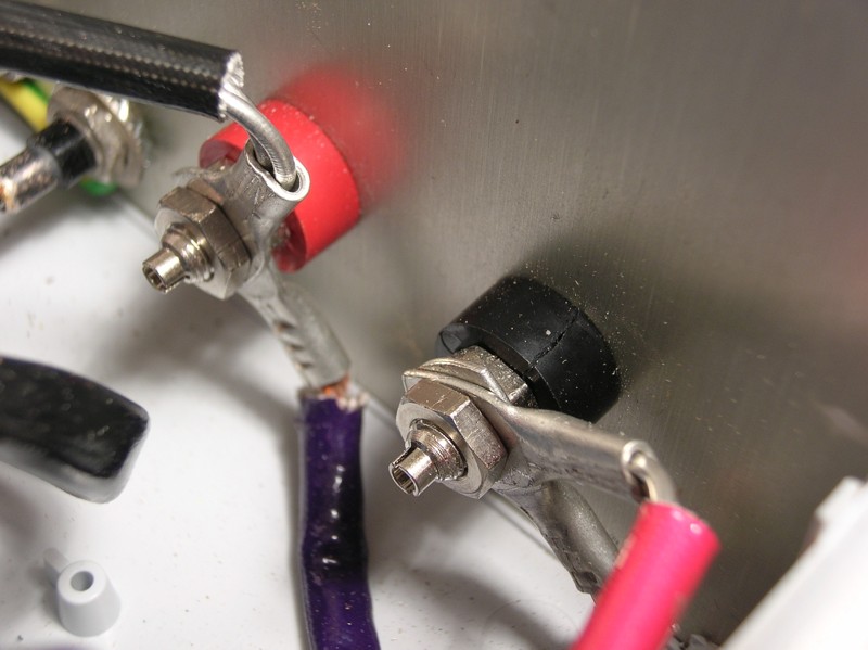
Viewing the front panel's back side, you can see how sturdy these connections should be. Take a lot of care when connecting the wires, as bad connections can be life-threaths. Avoid any risks of touching high-tension parts, of short-circuits, of wires getting loose, ...The foot switch should be connected well, too, as it switches the high-tension part.
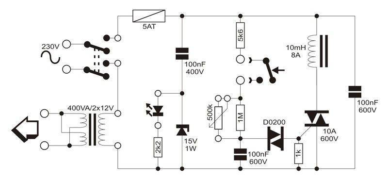
The scematic of the regulator shows this switch doesn't have to control a lot of current, but relatively high voltages. The power part of the dimmer has to resist at least 3 times the nominal input voltage, as the large transformer produces large inductive voltages. Although this transformer produces max 400VA, our resostance soldering can cause higher currents. 10 amps for the triac is fine, a slow 5amp fuse will protect the electronic parts.
 |
|
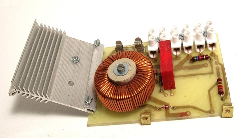
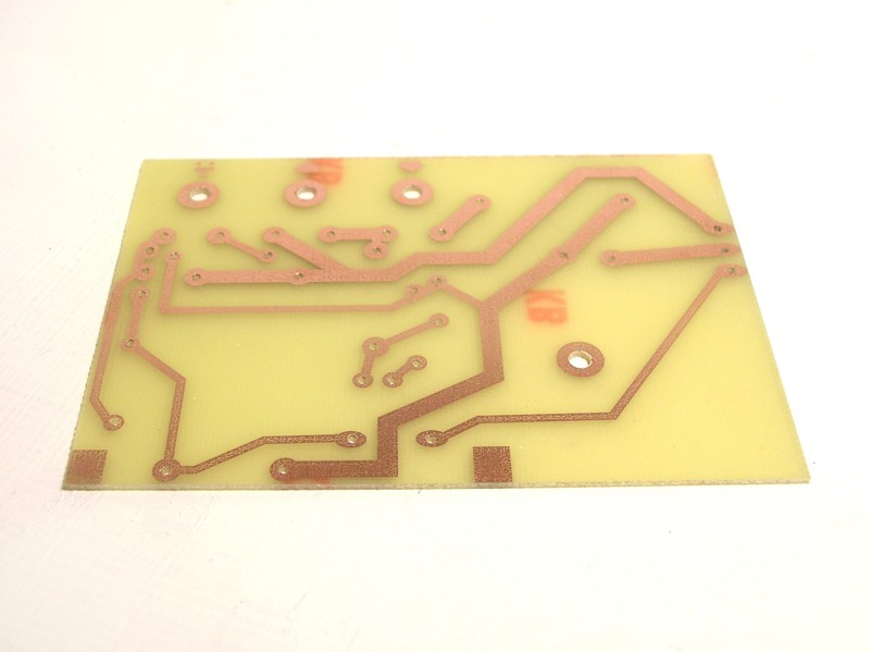
As the triac switches a lot of current, it should be cooled. A piece of metal, carefuly attached, sinks the heat. The printed circuit board shouldn't cause too much trouble to build, as long as you take very good care of electrical and mechanical safety.
 |
|
The circuit board is ready and mounted in the cabinet. As the connections are located at the upper side, the further wiring is made easy. The fuse is located on top as well, so it can be replaced easily if needed (I still have the first fuse bulb, after several months of intensive soldering).
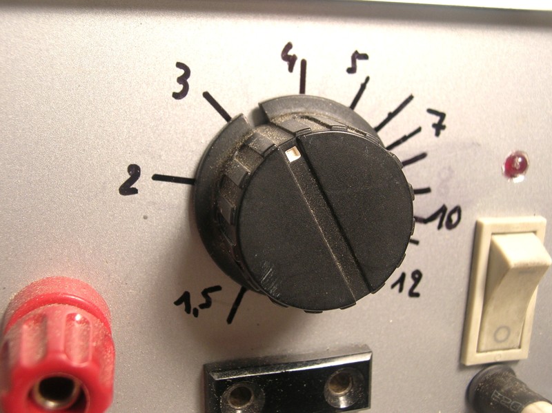
The front panel needs some kind of scale indication, and this was done using a felt-tip pen and measured output voltages. These marks allow me to repeatedly adjust the device for the different soldering circumstances.
 |
|
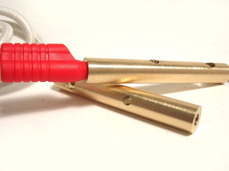
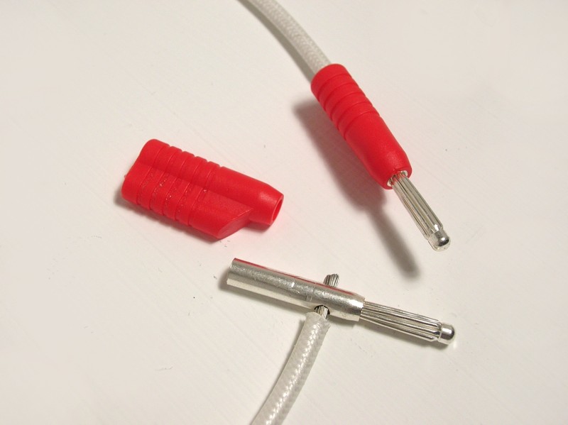
The cables and connectors should be excellent conductors, and should resist 50 amps of current. Clamps must be sturdy, battery-clamps are affordable and easy to obtain.
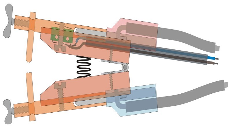
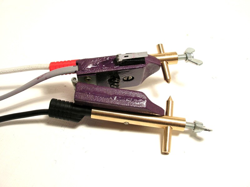
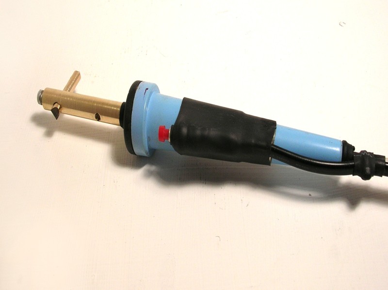
The more precise soldering jobs need a home-built clamp, scetched above. Each part of the clamp has one pole of the current, different types of contacts can be screwed into this. A spring holds the points apart, the wood isolates the electricity. A small built-in switch controls the sodlering period.
 |
|
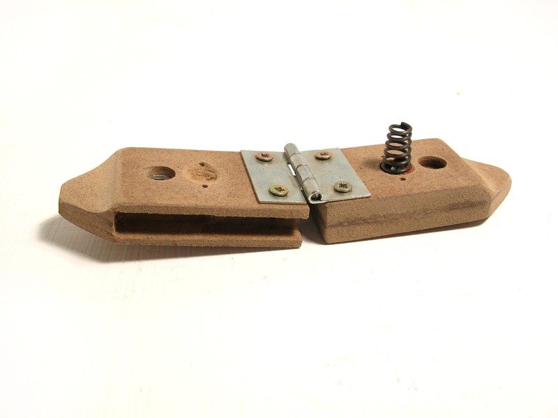
Two scarp pieces of hardboard are milled to shape: An outisde gutter holds a 10mm thick, round brass profile in place. Another gutter on the side makes room for the witch and its connection wire. On the inside, the spring is attached, as well as a hinge. An M5-sized-hole alows a bolt to secure the large brass profile.
This brass profile, about 8cm long, is milled as well: A 5mm angular hole will hold the soldering pins, using a vise mounted at the top end. Aanother angular M5-hole for the bolt mentioned earlier, a 4mm wide hole at the back end allows a connector to be attached.
 |
|
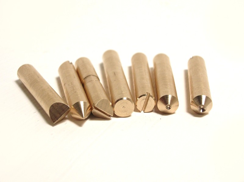
Starting with a 5mm thick round brass round profile, different types of sodlering points can be milled. The small microswitch is soldered to a connection wire and placed in the side-gutter, some epoxy taking care of insulation.
 |
|
When using a conductive base for resistance soldering, we need some kind of tool for applying the other pole of the current. This can be a modified electrical soldering tool. I used the same mechanical system as for the precision clamp, allowing exchangeable soldering tips.
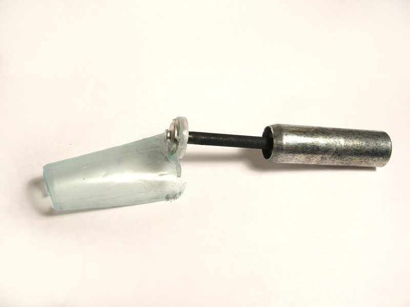
The second method of resistance soldering uses a "bad" conductor, placed very close to the future soldered joint. Ths conduxtor gets very hot, heating the nearby parts and thus melting the tin alloy.This "bad" conductor is a carbon stick, as can be found in an old-style battery. The smallest AAA-type batterie have 3mm thick carbon rods, the other ones have a 5mm thick one. Dismantle the battery, and with a bit of luck you can pull out the carbon.
 |
|
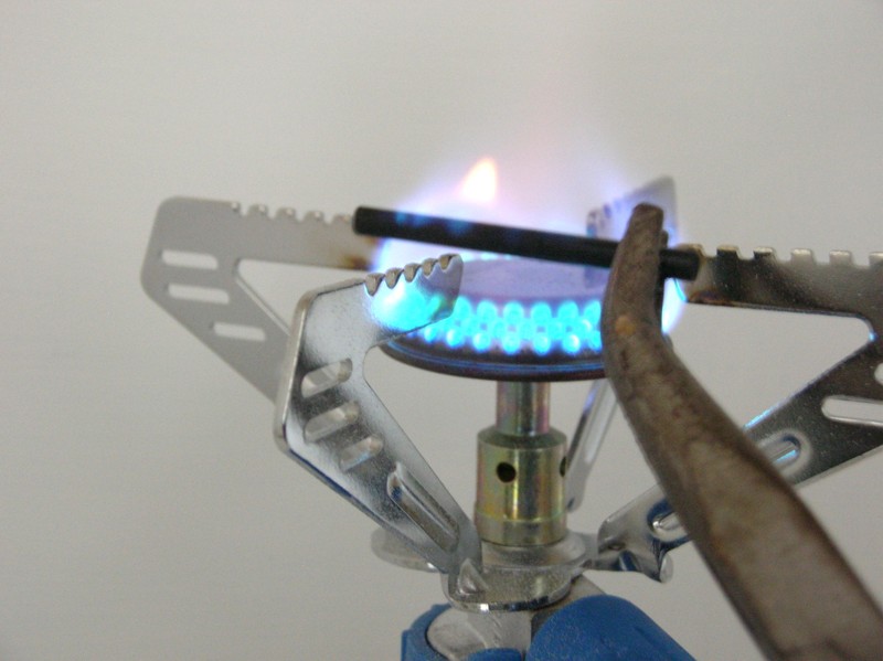
This carbon stick is soaked with a chemical fluid. Removing this is nescessary, and easily done by burning it out: Using a gas flame and a solid pair of tweezers, burn the stick untiol the yellow flames are gone. After cooling, you can shape it with a pencil sharpener or some sanding paper.
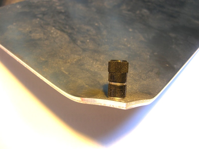
For using the bolt-like heater, a conductive "ground" is useful. I used a thick aluminium sheet and inserted a connector at one corner.
 |
|
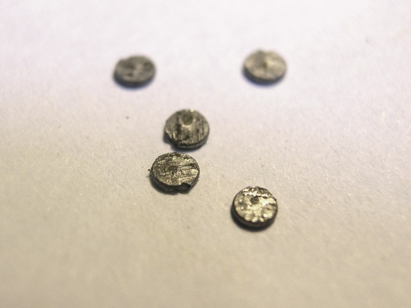
What's needed with every soldered joint, is the alloy. As resistance soldering is a very fast method, it's impossible to add it during heating. So, we place the tin very close or between the future joint, but this means preparing it a bit.
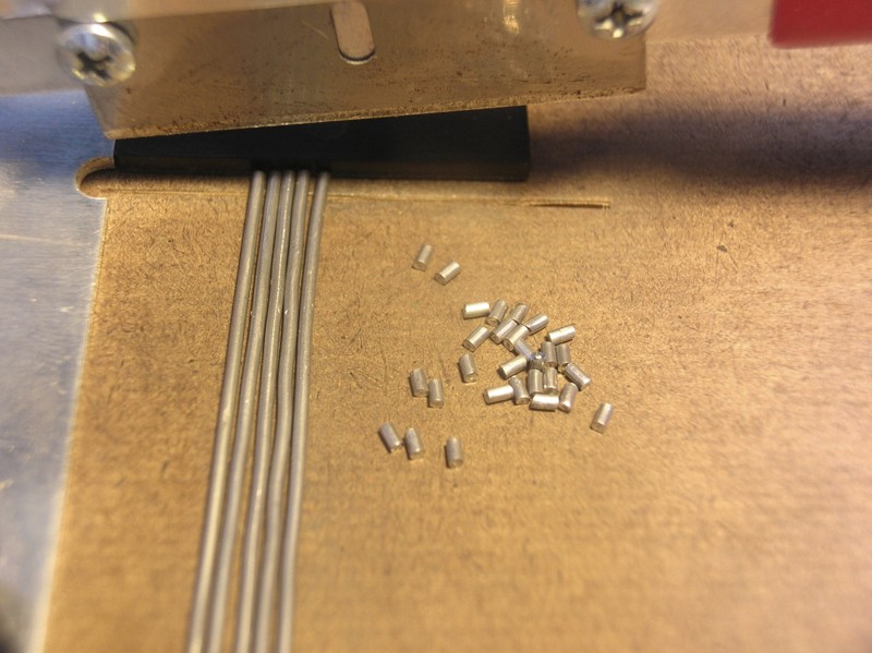
Using resin-core solder, cut small (about 1mm) cilinders off. We squash them between a pair of pliers or with a small hammer, to get very flat disks with the resin-core in the middle. These will be placed between the joint to be made. As they are very thin, during heating (with a bit of pressure) no open area appears, so we cause no sparks.
 |
|
To allow the alloy to float well, we dip these disks in some flux. The resin-type flux is best, as it is a little sticky and keeps the tin in position. When the joint has a large conne ting surface, it can be nescessary to place more of these disks.
With the parts placed, the disk in place, it's important to put a bit of pressure on the joint. When switching the current, the tin melts and the space now freed could cause a spark, burning the surfaces. Some pressure applied immediatly fills this gap.
A good joint should be done in about one second. Adjust the power to achieve this. Bare in mind that a sharpened coal-point has a higher resistance, and needs less current. The carbon cools relatively fast, your joint probably cools even faster.
 |
|
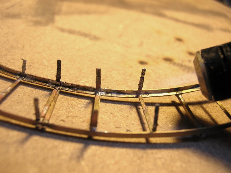
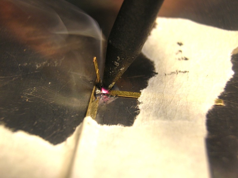
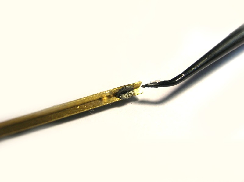
In part 1 of this series, I described soldering a feeder to a rail. A resistance soldering device is the best way to do this. Preparing the joint is identical. A thick soldering paste, heated with a sharpened carbon stick works excellent. The other pole of your current source is attached to the rail. to Use the coal rod to press the sire in place and switch the current for about one second.
I use the double-poled clamp mostly for joints where we can't press the part against a solid surface, because the parts are to fragile. You'll probably have to adjust the clamp parts to get a nice fit. Use a brass "ground" and a coal "hammer" to clamp the parts. Preparation and switching current is performed as above.
| ©2009 Gerolf Peeters - updated 15.12.2010 | See: Moulds - Etching |