Downhill breaking system
This appeared in Modelspoormagazine 76 and 77. More pictures and text there...
Most model railroads have a yard where trains are re-composed. After all, this encreases operating fun. A downhill fiddle-yard, where cars are sorted using gravity isn't built often, as the car's speeds are difficult to control. I might have found a sollution for this...
Re-arranging trains is mostly done in a dedicated yard. Incoming trains are split up, the cars are sorted and coupled to form an outgoing train. Especially major yards have a downhill sorting system. In real world, controlling the speed of a free-running car is difficult, too. The car should reach the rest of the consist as exactly as possible. Stopping too soon makes re-coupling harder to do, stopping too late might damage cars and their load.
A scale-model beaking system - how can this be done?
A well-working model breaking system should no just look good, but should accomplish a precise downhill speed of the cars. This isn't easy to do, and the proposed system was the result of several months of thought. I finaly decided to use brush hairs, gently stroking the car's axles. It isn't an easy sytem to build, but I guess people who decide to build a downhill fiddleyard aren't newbees in model railroad building.
Don't expect a fully automatic system, however. Although
it's possible to make this with the presented system, some measuring devices and a computer system, I opted for a semi-manual control to increase fun while operating it.
|
I'll explain the breaking unit first: a flexible material gently strokes the wheel axles and thus reduces the car's speed. The drawing shows a piece of track with a passing wheel. At left the break is up and active, at right it's down and invisible. The brush hair can be pushed up 10mm.
These units are built in three groups: one at the incoming part of the track, one in the middle and a third group near the end of the track. This way, the location of the speed reduction can be selected.
|

This illustration shows full-breaking at the back of the track. On the track's middle part, breaking force is "medium". This position is fine for light cars that should roll until the end of the track. The drawing shows a 5-5-5 distribution, but in fact I doubled the amount of hairs and put more units in front than in the back. This way, the distribution really is 14-10-8, 32 hairs on each track.
The breaking units are fixed to a frame, moveable on the front and the back side. The movement itself is accomplished with a home-built servo motor.
|
|
A cross-section drawing shows the gears and their position towards the frame a bit better. The larger gear is needed to let the measuring potentiometer of the servo system have its maximum useful turning angle.
On the frame, of which a section is drawn at the top, you can spot a connection with one of the breaking units.
|
|
In my situation, there are 5 fiddleyard tracks, at an 18 degree angle with the layout's supporting frame. Because of this, the breaking system's metal frame could not be built in a rectangular shape, but had to follow this angle.
The drawing shows the frame with the locations for the breaking units, as well as the positions for the servo motor constructions. This scetch, together with the previous ones, allowed me to get to work...
|

For each breaking unit, you need one 2mm thick tube, 17mm long and two 1mm thick tubes, 14 and 19mm long. The shortest 1mm tube is soldered into the 2mm tube, overlapping 2mm for a solid constrution. A tool I previously made for my lanterns was very useful for cutting and soldering these little tubes.
|

Use very little solder and heat the joint very shortly, so no solder ouzes into the small 1mm tube opening. The result of this construction should resemble the photo. For each track, you will need about 30 of these.
|

To position the tubes exactly, we make a drilling mould from 2cm wide pieces of 1mm thick epoxy sheet. One piece should fit exactly between the rails, three others are glued on top of them with cyanoacrylate glue. In the middle of this "sandwich", we drill two 1mm wide holes, 10mm apart. These holes should be drilled at a perfect 90°angle, so you must use a drill support.
|

Because of this thick drilling mould construction, we can now drill through the subroadbed by hand, at the right place and angle. Drill the holes between the track ties.
Starting from the layout's underside, widen these holes with a 2mm drill to a depth of 8mm. This way, our soldered tubes can be shoved in from beneath to their right depth.
|

If you drilled correctly, the tubes should fit tightly in the holes. For now, the tubes are quite visible between the tracks, but their top ends can be camouflaged with a felt tip marker. After this little "paint work", press the tube down so it sits even with the track's ballast.
Once all tubes are at their correct depth, use some glue to secure their position.
|

Measuring the exact dimensions of the supporting frame is best done "live" under the layout. Fix the 4x4mm brass U-profiles in their correct position with some tape and mark the places where they should be soldered and drilled.
|

Drilling is done with a drill support and guidance rail. Holes through both sides of the U-profiles will guide the breaking system's supports.
To solder these brass profiles, I used a miniature torch, tinning fluid and resin-core solder. |

Once the frame is soldered, check its form under the layout. You will probably have to make some adjustments. With this done, we can start building the servo motor support system.
|

We again use 1mm thick epoxy sheet, and cut 35mm wide pieces. Cut and drill them to shape using the photo as an example: it shows the sheets for one of both servo systems.
Some small brass tubes are also needed: for each servo, these are two 2mm thick and 15mm long ones, two 3mm thick and 6mm long and a longer 4mm tube, its length depending on the number of tracks. Furthermore, we need some gears, and two 10k linear potentiometers. |

The servo motor driver has been used before when I made turnout drivers. These motors can be found cheaply inside a battery-driven disco-mirror-ball-driver.
A last part for the servo supporting system are two pieces of phosphor bronze springs, 5mm wide and 10cm long, drilled and bent to shape.
|

After drilling two matching holes in these bronze springs, we can solder them in place. Using resin-core solder and our little torch, this is done in no-time.
|

Some pieces of scrap styrene and our previously made pieces of epoxy are used to build the servo system supports. The picture shows part of the support at the motor side. The potentiometer gets another support, the other end of the main driver axle gets another.
|

The last support is for the motor case itself. It is made from the smallest piece of epoxy and one a bit larger, held together with pieces of 2 and 6 mm thick square styrene rods. The photo shows the “sandwich”.
|

This part is now glued to the motor's gearbox. To allign it at the right spot, use the support we made first, but don't glue it yet. Use on of the small 2mm brass tubes to get the alignment right, while the cyanoacrylate glue between the small support and the gearbox sets.
|

Before attaching the second support, we must glue a small gear on the motor's axle. The first support indicates where this gear should be placed. Using a bit of instant glue, the gear is fixed. A 3mm brass tube can be shoved over the smaller tube, but don't glue it, as it should be able to roll around the smaller one.
|

Now the larger motor support can be glued to the previous one. The small brass tube can be fixed using a drop of instant glue.
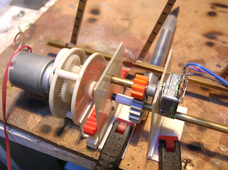
On the potentiometers' axle, we glue another small gear, as close as possible to it's housing. The large gear is now glued to the longest brass tube.
|

Over this brass tube's end, a larger piece of styrene tube is shoved and glued. Checking the right distance between the large gear and the one on the potentiometer, this device can be screwed in place. Now we can construct the end support for the long brass tube, similar to the motor support using a 2 and 3 mm small brass tube as a "roller".
|

The last of the mechanical preparation is gluing the small end gear on it's place. We need the frame to find the right position, as it holds the bronze springs which support the flat gear parts.
Before gluing this gear, make sure the potentiometer's support is placed over the large brass tube!
|

To start with the electronics of our servo system, I show the home-designed schematic first. At left, you see the two potentiometers, one of which is connected to the motor. The position of the two potentiometers is compared with two operational amplifiers, connected as a "window comparator": they measure the difference between voltages, and send steering signals to the power part, located at the right in the schematic.
|

The print-layout shows the components: at left, the 6 potentiometer connections, the measuring unit in center and the power drivers at right. The components are drawn transparant, so you can see the wiring through them. For the less experienced electricians, I'll explain the further building steps.
|

After etching and drilling the PCB, we start with mounting the smallest components: resistors and diodes. The diodes need to be soldered in the right direction.
After this, the condensor and the IC can be connected. The larger condensor and the IC should be placed with the correct polarity, too.
The last parts, the power transistors, should also be placed in the right direction. Use the next picture as a guide.
|

The connecting wires can now be soldered to the PCB. I used power feeder colors according to the colors I use for the rest of my layout, and rainbow-coloured flat wires for the potentiometer and motor connections.
After this, we can check if all works fine. Connect both potentiometers to the PCB. By turning the controlling potentiometer, the engine should rotate until the other potentiometer reaches the same position. You will probably need to adjust things.
|

Now we can connect the servosystem mechanicaly to the brass frame. Shove the measuring potentiometer a bit aside, clamp the entire servo system on your desktop and let the flat gears "come into" the servo system by using the steering potentiometers. Once the gears reach the right position, put the measuring potentiometer in place. Now you can thoroughly test the servo system.
|

After this final test, we can mount everything under the layout. Start by roughly positioning everything, fine-tune the placement of the parts and clamp them to the layout supports.
|

The system should be positioned at the right depth, so use some fitting piece of scrap material as a reference. Now we can, step by step, fix each servo system support with some small wood screws. When this is done, we can finish the braking units assembly by connecting them to the frame. |

The remaining thin tubes are placed as deeply as possible in the composed tubes we glued in the holes earlier. Put both servo systems in their highest position. Through the holes in the brass profiles we can now place copper wires, which we solder to these tubes' ends. Heat the joint very short, so the deeper soldering joint doesn't re-melt. The picture shows the steps from right to left.
|

We got the actual braking wires from a cheap cleaning brush. The clipped-off, flexible wires are shoved into the small tubes with a bit of glue at their end. |
Place the breaking system in the lowest position, and cut the wires to the right length: flat with the ties. When putting the system in the upper position, the brush hairs come out nicely and gently reduce your car's speed.
|
After this "haircut", our system is ready to use. The building of this system isn't very obvious, neither is using it. Nevertheless, after some exercising, it is very much possible to make your cars stop at the right spot.
Thanks for reading this long story, and I hope you've learned something from it!